

Wiring duct has to do more than make a control panel look tidy. It must support an efficient assembly process, keep conductors manageable while covers are open, provide practical exits near terminals, and remain serviceable after the equipment reaches the field.
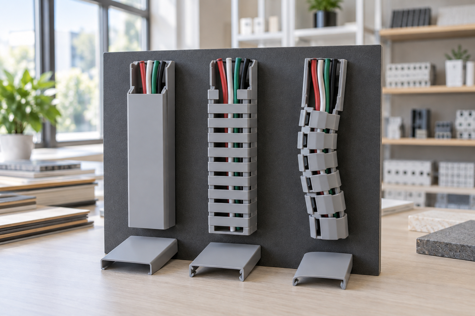
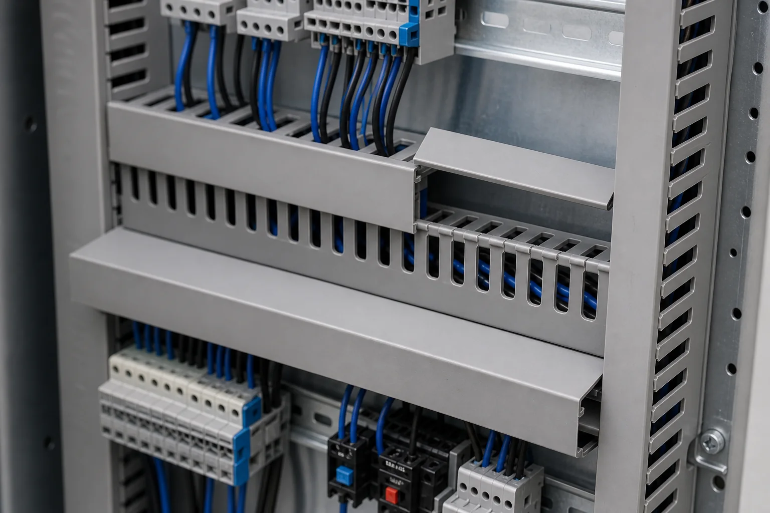
For some layouts, standard slotted duct provides the right balance of access and flexibility. Other panels benefit from a connected-finger profile, commonly described as sealed wiring duct or sealed insulated wiring duct. In this design, the tops of the side fingers remain joined by a continuous rim. The slots still allow individual conductors to exit, while the connected edge adds side-wall support and helps retain wiring.
This guide explains where that construction can add value, where it may make fabrication less convenient, and how OEM buyers, panel builders, and distributors can specify it without relying on a product name alone.
What Is Sealed Insulated Wiring Duct?
Sealed insulated wiring duct is a slotted channel used to route conductors inside electrical cabinets, control panels, automation equipment, and similar assemblies. SMK’s product uses rigid flame-retardant PVC, a removable snap-on cover, and a continuous connected rim across the tops of the side fingers.
The word “sealed” describes the connected-finger profile. It does not mean that the duct is watertight, airtight, dustproof, or a substitute for a rated enclosure. It also does not create electrical shielding or provide environmental protection on its own. Those requirements belong to the complete cabinet design and must be verified separately.
The main practical difference is mechanical geometry. On an ordinary slotted duct, each finger is separated to its top edge. On a connected-finger duct, the top rim ties the fingers together. Conductors leave through the slots below that rim, and the cover closes over the channel.
When Does a Connected-Finger Design Make Sense?
The design is worth evaluating when wire retention and side-wall stability matter during assembly or maintenance.
Vertical routing with the cover removed
Technicians often remove several duct covers while wiring or testing a panel. In a vertical route, loose conductors can press outward and make the work area harder to manage. A connected upper rim can help keep the bundle inside the duct while individual wires are routed through the slots.
That benefit should be verified with the actual conductor mix. Heavy bundles, large cables, sharp bends, or an overfilled duct can still create outward pressure. The profile is a routing aid, not a reason to ignore capacity or bend requirements.
Repeat-build control panels
For an OEM producing the same cabinet repeatedly, consistent routing can reduce variation between workstations. A defined duct model, cut list, cover list, and exit map give assemblers a repeatable path. The connected rim can support this process when most wire exits are known before production.
Long runs or handling before final wiring
Duct sections may be cut, drilled, mounted, and handled before every conductor is installed. Greater side-wall support can be useful during these steps, particularly on taller profiles or longer sections. Buyers should still test the chosen size because rigidity depends on the complete geometry, material, cut pattern, and mounting method.
Panels where orderly containment is prioritized
Some buyers place high value on keeping wiring contained when covers are temporarily removed for inspection. Connected-finger duct can be a practical option, provided technicians can still reach the required circuits and remove covers without obstruction.
For application context, review SMK’s control-panel and wiring-duct solutions.
Where Standard Slotted or Pull-Apart Duct May Be Better
Connected fingers are not automatically the best option for every route.
Standard slotted duct may be easier where installers need to remove individual fingers, create wide side openings, or change exit positions late in the build. Pull-apart duct may suit compact assemblies and development work where wires are inserted, removed, or rerouted frequently without a separate cover.
The decision should follow the task:
| Panel requirement | Design to evaluate first | Reason to sample-test |
|---|---|---|
| Known routes, emphasis on retention | Connected-finger sealed duct | Confirm wire insertion, exit access, and cut quality |
| Frequent wide exits or field modification | Standard slotted duct | Confirm finger removal and finished edges |
| Repeated wiring changes in compact spaces | Pull-apart duct | Confirm flexibility, holding action, and mounting |
| Mixed requirements in one cabinet | Hybrid layout | Confirm transitions, cover access, and BOM control |
SMK’s article on pull-apart versus slotted wiring duct provides a fuller comparison for change-intensive layouts. Its broader wiring duct selection guide covers capacity, material, circuit separation, and cabinet space.
Plan Wire Exits Before Cutting the Duct
A connected top rim makes exit planning more important. The engineering team should map the route before the workshop cuts production quantities.
Start with the cabinet layout, terminal plan, wire schedule, and component clearances. Mark where each circuit group enters the duct, travels through it, and exits toward a device. Review terminal blocks, breakers, relays, PLC modules, drives, power supplies, communication hardware, and door wiring separately.
At each planned exit, check:
- The conductor or cable outside diameter
- The number of wires leaving together
- The distance from the slot to the termination point
- Required bend space and manufacturer guidance for the conductor
- Access to terminal screws, labels, and test points
- Separation required between power, control, safety, analog, and communication circuits
- Whether a wider local opening must be fabricated
Do not cut the connected rim casually with side cutters and leave a sharp or cracked edge. Agree on the cutting tool, cut location, edge-finishing method, and inspection standard during sample approval. If many wide openings are needed, a standard slotted profile may be more efficient than repeatedly modifying a connected-finger profile.

Size Each Duct Section from the Actual Wire Route
Catalogue wire counts are useful for initial comparison, but they are not universal fill limits. Two panels with the same number of conductors can require different ducts because insulation thickness, markers, ferrules, shielded cables, bend locations, crossings, and spare circuits change the usable space.
Calculate each route separately. A main horizontal section can collect conductors from several vertical branches, while a short route beside one terminal row may carry far fewer wires. Preserve enough free space to install, identify, trace, and replace conductors without forcing the cover closed.
SMK lists its sealed insulated wiring duct in multiple width and height combinations from 25 × 25 mm through 120 × 100 mm, with a standard listed length of 2 m. The product page describes rigid flame-retardant PVC and a typical working range of −20°C to 65°C. These are catalogue references; the selected model, material, performance documentation, color, and order-specific values should be reconfirmed in the quotation.
Review the current sealed insulated wiring duct range and compare it with standard insulated wiring duct before freezing the BOM.
Build a Useful Sample Approval Test
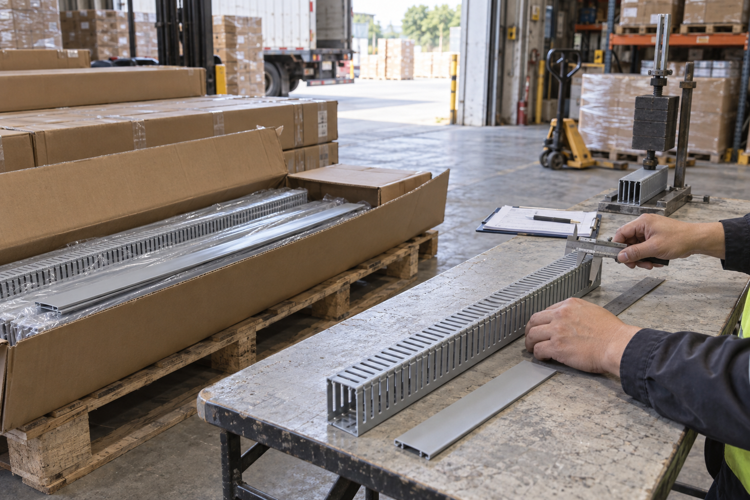
A loose sample on a desk cannot show how a duct behaves in a real panel. Create a short trial section using the proposed mounting plate, fasteners, tools, wire mix, markers, and cover clearance.
The trial should check:
- Dimensions: Measure the external width and height, usable internal space, slot geometry, base thickness where relevant, and cut length.
- Mounting: Confirm hole positions or the planned drilling method, fastener head clearance, flatness, and alignment on the mounting plate.
- Cutting: Cut both the base and a planned side exit. Look for cracks, excessive whitening, burrs, or rough edges that could contact insulation.
- Wire insertion: Route the smallest control wires, the largest expected conductors, and any marked or shielded cables included in the design.
- Retention: Remove the cover on horizontal and vertical samples. Observe whether the connected rim keeps the normal bundle manageable without compressing it.
- Cover fit: Close and reopen the cover after the duct is loaded. Confirm that it seats consistently and that nearby devices do not block removal.
- Service access: Trace and replace a representative wire. Make sure labels, terminals, and test points remain accessible.
Record the approved sample, supplier model, dimensions, color reference, packaging, and inspection points. For repeat production, add photographs and a controlled drawing or cut list so purchasing and assembly teams use the same reference.
What to Put in a Sealed Wiring Duct RFQ
“Grey sealed wiring duct” is not enough for a comparable quotation. Send a structured request containing:
- Required width × height and standard or custom cut length
- Estimated quantity by size
- Connected-finger profile requirement
- Slot width, pitch, and exit-opening needs
- Cover type and whether covers are included in the quoted quantity
- Material and color
- Operating temperature and nearby heat sources
- Panel type and installation orientation
- Conductor schedule or representative wire-size range
- Required declarations, reports, or market-specific documents
- Packaging, labeling, private-label, and carton requirements
- Sample quantity and approval tests
- Dimensional tolerances or drawing requirements
- Delivery destination and requested schedule
Ask the supplier to identify assumptions and exceptions instead of silently substituting a nearby profile. Confirm whether base and cover are packed together, how 2 m lengths are protected from bending in transport, and how partial cartons or mixed sizes will be labeled.
If the duct will be installed inside a custom PLC control cabinet, include the internal layout, circuit groups, component list, and access requirements in the cabinet review rather than treating the duct as an isolated purchase.
Common Selection Mistakes
Avoid four shortcuts that create preventable problems.
First, do not interpret “sealed” as an enclosure protection rating. Second, do not select a model from wire count alone. Third, do not assume connected fingers remove the need for cover clearance, bend space, circuit separation, or correct mounting. Fourth, do not approve a bulk order based only on appearance.
The useful question is not whether sealed wiring duct is generally “better.” It is whether its connected-finger geometry supports the exact routing, assembly, inspection, maintenance, and supply requirements of the panel.
Request a Model Review Before Bulk Ordering
For a practical recommendation, send SMK the cabinet layout, required duct sizes, conductor information, quantity, target market, documentation needs, and packaging requirements. The team can review available models and sample requirements before the order is finalized.
Contact SMK Cable Management to request a wiring duct quotation.
Frequently Asked Questions
Is sealed wiring duct waterproof?
No. In this product name, “sealed” refers to the connected tops of the side fingers. The duct has cable-exit slots and a removable cover, so it should not be treated as watertight, airtight, dustproof, or equivalent to a rated electrical enclosure.
What is the main benefit of connected finger tops?
The continuous top rim adds side-wall support and can help retain conductors while the cover is removed. The benefit is most relevant when the exit pattern is known and the actual wire bundle has been tested in the selected size.
Can I remove part of the connected rim for a wider cable exit?
A wider opening may be possible with an approved cutting method, but the result must be checked for cracking, sharp edges, reduced side-wall support, and adequate cable clearance. If many wide exits are required, compare a standard slotted profile before ordering.
How do I choose the correct duct size?
Use the outside diameter and quantity of conductors in each route, then account for markers, ferrules, crossings, bend space, installation access, and future changes. Treat catalogue wire counts as references and confirm the final choice in a loaded panel sample.
What should a distributor verify before a repeat order?
Keep the approved model, dimensions, material and color reference, cover fit, sample photographs, packaging, labels, carton quantity, and required documents with the purchasing record. Ask the supplier to confirm any changes before production.
Related Products
Products for This Guide
Review specifications or request pricing for the products most relevant to this article.
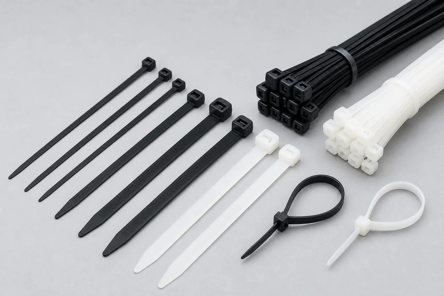
Standard Nylon Cable Ties
The most widely used cable fastening solution for electrical, factory, construction, electronics, and wholesale markets.
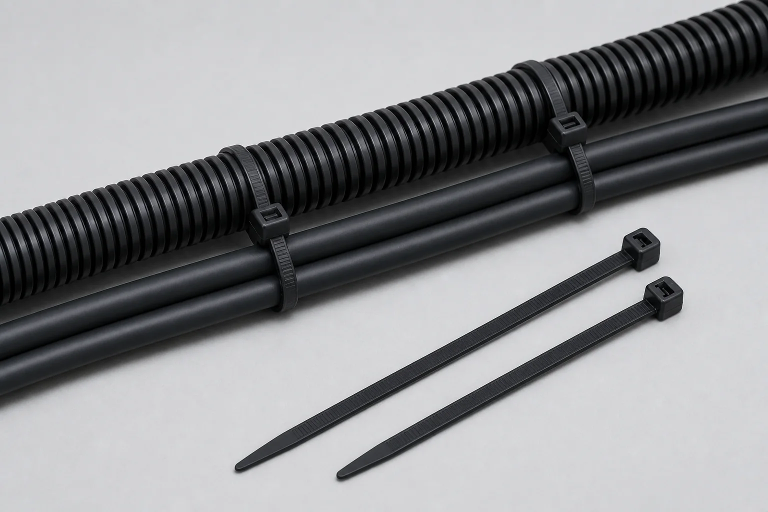
UV Resistant Cable Ties
Weather-resistant black cable ties for solar, telecom, outdoor engineering, and power installations.
Insulated Wiring Duct
Standard slotted PVC wiring duct for organized routing inside control panels and electrical cabinets.